
Arduino uno pinout stepper driver code#
Example 1: Basic Arduino code (no library)

This will not be an efficient way to drive the motor, but is a good way to get started and get a feel of what it takes to spin the stepper motor. There are two Arduino libraries that help to manage stepper motors and I will cover both in the examples below, but first I like to test out my set up with some basic Arduino code. Note that stepper motors can draw significantly more current than the Arduino 5volt reail can source, so you should get a separate power supply for your motor, and remember to connect all grounds. H-Bridge Input 3 -> Arduino Digital Pin 6īoth Enable pins on the H-Bridge are connected to 5v (always enabled). H-Bridge Input 2 -> Arduino Digital Pin 4 H-Bridge Input 1 -> Arduino Digital Pin 2 If you are going to follow along the examples below, you can connect the H-Bridge to your Arduino as follows: Here is a diagram of the circuit I am using in all of the examples below (Source: ): You will also need a prototype board, some hook-up wires, an Arduino Uno, or compatible mocrocontroller, a computer with the Arduino IDE loaded and of course, a stepper motor. The easiest way to do that is with an H-Bridge IC, like the L293D ( datasheet ), or the SN754410NE ( datasheet ). You need to be able to reverse the current in the two coils A1A2 and B1B2, much like reversing the current across a DC motor to get it to spin forward and backwards. Step 2: Prototype the circuitīipolar stepper motors require a bit more complex electronic control circuit than unipolar steppers, like the 28BYJ-48.

Once you figure out the two center taps, you can simply mark them and ignore them, as you will leave them disconnected, focusing on the remaining 4 wires instead.

You can do that following the same tutorial on stepper motor wiring mentioned above. If you got your motor from a mystery eBay special, or from an old printer, then you need to do some testing with a multimeter. Once you figure out how your stepper is wired, remember the colours of the 4 wires, or mark them.Įven if your stepping motor has 6 wires, you can still control it like a four wire stepper motor, you just need to identify the center tap wires. All we need here is to see how the 4 wires coming out of your bipolar stepper motor are paired in the internal wingdings. If you have some documentation about your motor than you are set.
Arduino uno pinout stepper driver how to#
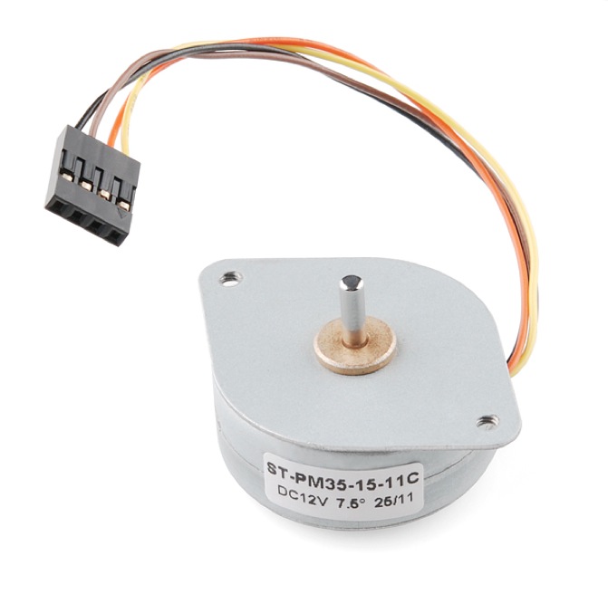
It is a well known fact that Stepper motors are awesome! The only downside is that they can be a bit trickier to get going than servos and plain old DC motors. If you are interested in the inner mechanics and theory of stepper motors, check this excellent post on PCB heaven. If you happen to have one of the cheap little 28BYJ-48 steppers with 5 wires and a little driver board with them, check this tutorial instead. Here, I will focus on how to get a bipolar stepper motor (typically 4 wires) working with Arduino and a H-Bridge IC like the L293D, or the drop in improved replacement – SN754410NE.


 0 kommentar(er)
